BeamLab 2.3 is out now with great new features and lots of improvements! This time we significantly enhanced BeamLab’s capability to work with externally generated 3D refractive index distributions. Read on to learn more about this feature or directly jump to the release notes.
Creating a waveguide’s refractive index distribution by importing 3D arrays
In our previous release we introduced the possibility to create waveguides based on externally generated and imported two-dimensional images. This time, we complemented this functionality by adding a new waveguide function dubbed importedwaveguide3d that allows one to import a three-dimensional (3D) refractive index distribution in form of a 3D array. In addition, we also enhanced BeamLab’s indexplot function to allow one to export any three-dimensional refractive index distribution generated by BeamLab in form of a 3D array and save it in a MAT file. In other words, one can now not only import an arbitrary 3D refractive index distribution that has been generated independently of BeamLab and is represented by a numeric 3D array, but also create much more complex waveguide structures with BeamLab (not available through any single built-in waveguide function) by concatenating multiple structures generated by BeamLab’s built-in waveguide functions. In the following example, we use this feature to generate a waveguide structure that demonstrates the coupling of light from a standard silica fiber core with a diameter of about 9 µm to a silicon-nitride (SiN) planar waveguide with a refractive index of ~1.9, a width of 1.5 µm and a thickness of 0.5 µm. To do so, we first generate a fiber tip by using BeamLab’s singlecore function. The fiber tip consists of a tapered fiber core suspended in air. In a second step, we then generate the planar waveguide by using BeamLab’s rib function where the SiN waveguide is placed on top of a silica substrate. The refractive index distributions of both waveguide structures are separately exported in form of 3D arrays to MAT files and then externally loaded and concatenated to form a new waveguide structure that represents the fiber-to-rib coupler consisting of both the fiber tip and the planar waveguide. Finally, we import this newly generated 3D array to perform the calculation for the beam propagation.
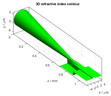
3D refractive index contour plot of the waveguide structure consisting of both the silica fiber tip and the SiN planar waveguide
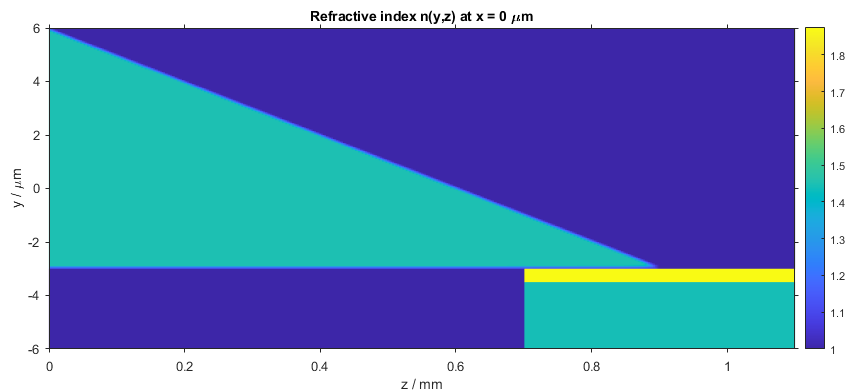
Two-dimensional refractive index distribution in the y-z plane
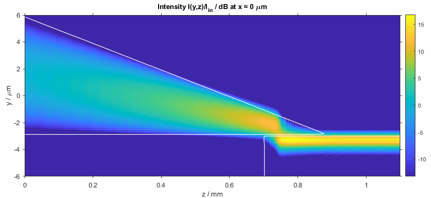
Two-dimensional intensity distribution in the y-z plane demonstrating how the light in the fiber core is efficiently coupled to the planar waveguide
Exciting new demos
In this release we also expanded our demo library. Besides the fiber_to_rib demo discussed above, we added a demo dubbed photonic_crystal_fiber_twisted that shows how to calculate beam propagation in a twisted photonic crystal fiber. Photonic crystal fibers (PCFs) come in various forms and types. In contrast to standard fibers, where light is guided by means of total internal reflections at the interface between the core and cladding due to different refractive indices, PCFs are made from a single material (usually silica) and the guiding mechanism is due to an interference or a photonic band gap effect emerging in a regular two-dimensional array of air holes (which structure-wise is reminiscent of photonic crystals) that surrounds a light-guiding core, e.g., a solid core formed by removing one air hole from the center of the air hole array.
The following movie shows light propagation in a PCF when illuminated with a Laguerre-Gaussian beam of azimuthal order 1 at the wavelength of 1 µm. The PCF consists of a solid silica core surrounded by 90 air holes with a diameter of 3.6 µm arranged in a triangular lattice with a lattice constant of 8 µm.
The next movie shows what happens when the solid core is removed by placing an air hole also in the PCF’s center. As expected, light in such a coreless PCF cannot be guided anymore and quickly scatters in lateral direction with increasing propagation distance.
For the final movie, a twist of 180 degree per mm was added to this coreless PCF, which brings us to the subject of the new demo photonic_crystal_fiber_twisted. When the PCF is twisted, it can be seen that the light tends to gather near the center of the PCF enabling a guiding effect although no core is present. This guiding effect depends on the twist rate but in general seems to be not as pronounced as it is case when a core is present.
Release notes
New features:
- Add new function
importedwaveguide3dthat allows one to create a waveguide whose 3D refractive index distribution is externally generated and imported via a MAT file or 3D array. - Add new function
farfieldplotthat allows one to calculate and plot the far field of a given near field distribution. - Add new function
pcolorgridconverterthat allows one to adapt the data stored in the output structure ofbpmsolverormodesolverto reproduce the intensity or field plots of x-y, x-z, or y-z slices by using thepcolorfunction of MATLAB®. - Add new parameters
Index3DOutputandIndex3DOutputFilenametoindexplotthat allows one to export the whole propagation structure in form of a 3D array. - Add new parameter
Index3DPlotXYSteptoindexplotthat allows one to adjust the resolution in x- and y-direction of 3D refractive index contour plots. - Add new parameters
DispersionOutputandDispersionOutputFilenamethat allows one to save the output of adispersionsolvercalculation to a MAT file. - Add new parameters
ReferenceCoreWidth,ReferenceCoreIndex, andReferenceCladdingIndexto waveguide functionscustomwaveguide2dandcustomwaveguide3dthat allow one to define a reference profile as index function that is internally adjusted according to these parameters. - Add new parameter
Figureto functionplotindexthat allows one to add the graphs generated byplotindexto a user-specified figure. - Add new parameter
Nameto functionplotindexthat allows one to display a user-specified material name in the figure legend. - Add new parameters
DopantMaterialandDopantPercentageto functionsgetindex,getmaterial, andplotindexthat allow one to define a doped material with a specified dopant fraction according to the mixed Sellmeier model. - Add new parameters
CalculationPauseandCalculationStopthat allow one to pause or stop abpmsolvercalculation at any arbitrary location on the z-axis. - Add possibility to evaluate the group index
Ngroupindispersionsolver. - Add possibility to display the magnitude, real part and/or imaginary part of the refractive index when generating refractive index slices with
indexplot. - Add new materials GeO2 and SiN to the material database.
New demos:
- Add demo
axiconwhich shows how a Gaussian beam is transformed into a Bessel-like beam when propagating through an axicon. - Add demo
photonic_crystal_fiber_twistedwhich shows how light is guided in a twisted coreless photonic crystal fiber. - Add demo
fiber_to_ribwhich shows the coupling of a fiber tip to a high-index planar waveguide.
Modified functions:
- Rename function
importedwaveguidetoimportedwaveguide2d. - Simplify input argument list of function
resizefield.
Enhancements:
- Set the default value of the parameter
MonitorStepsuch that the x-y distributions are displayed a minimum of 1 times and a maximum of 20 times per propagation section during abpmsolvercalculation. - Improve
dispersionsolverin terms of tracking the correct order of the eigenmodes during a frequency or wavelength scan. - Improve performance when determining the refractive index contour overlays for a
bpmsolvercalculation. - Improve documentation.
Bug fixes:
- Fix bug in
dispersionsolverwith respect to warning messages. - Fix bug in waveguide function
rib. - Fix bug in function
resizefield. - Fix bug in input function
gaussinput. - Fix bug in
indexplot. - Various minor bug fixes.