Fiber Dispersion
This BeamLab demo calculates the dispersion characteristics of a fused silica step-index fiber with a circular core. The scanning parameter can be either the normalized frequency V or the wavelength λ. Various dispersion curves can be plotted showing the normalized propagation constant, effective refractive index, mode field diameter, and effective mode area as a function of the normalized frequency or wavelength.
BeamLab demo: fiber_dispersion.m
In this example, the core of the fiber has a diameter of 10 µm and an index delta of 0.7%. The cladding consists of pure silica.
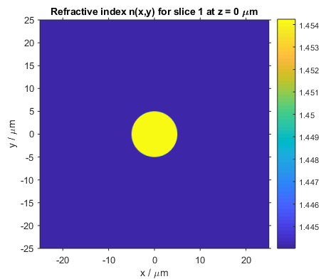
Refractive index profile of the circular fused silica step-index fiber
Calculations of the normalized propagation constant show the onset of higher-order modes with increasing normalized frequency as exemplified by the yellow (LP11 mode), green (LP21 mode), and light-blue (LP02 mode) lines in the following figure. The fundamental LP01 mode represented by the dark blue line exhibits always the largest propagation constant and has no cutoff frequency.
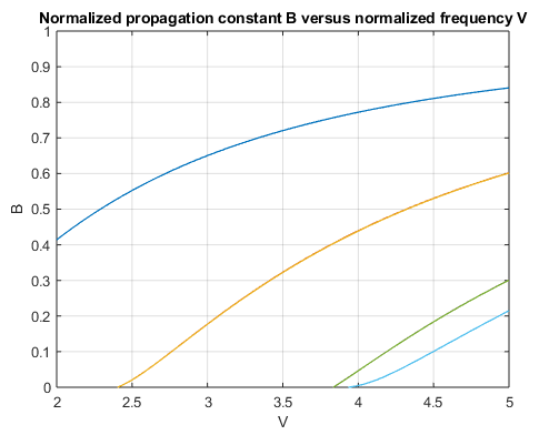
Normalized propagation constant of the circular fused silica step-index fiber
Calculations of the normalized propagation constant B are well suited for studying the fiber’s waveguide dispersion characteristic as any material dispersion, i.e., any dependency of the fiber material on the wavelength or frequency of the optical field, is canceled out by definition. Waveguide dispersion is thus known as the dispersion that arises from the mode’s spatial confinement in the fiber and is governed by parameters such as the core diameter, the index difference, and the shape of the index profile. To visualize the effect of both waveguide and material dispersion on the modal characteristics, the following graph shows the actual effective refractive indices of the first few modes. The refractive index of silica slightly increases with frequency (depicted by the dark orange line), and so does the modes’ effective refractive indices in addition to the increase observed from waveguide dispersion.
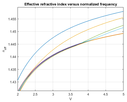
Effective refractive index of the circular fused silica step-index fiber
A second set of important parameters that is used to describe the spatial extent of a mode and thus the transmission performance of a fiber are the mode field diameter (MFD) and effective area. The original definition of the MFD, .e.g., by using the Petermann equation, was motivated by the fact that the fundamental mode of standard step-index fibers resembles a Gaussian beam and therefore the MFD could be related to the beam waist of a Gaussian beam. Although the same equation can be applied also to higher-order modes, the meaning and usefulness of defining a MFD for such modes however is not very clear. In such cases, the effective area may be the main parameter of choice. The effective area is a field distribution dependent weighted average of the area that is occupied by the mode and typically used as a measure of the fiber’s response to nonlinear effects.
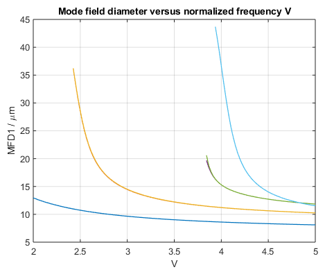
Mode field diameter of the circular fused silica step-index fiber
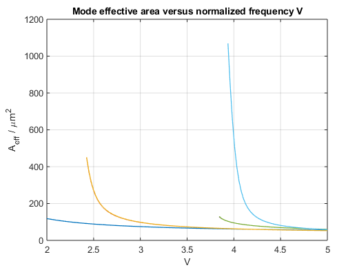
Mode effective area of the circular fused silica step-index fiber
About BeamLab
BeamLab is an award-winning set of simulation tools for beam propagation through optical devices and waveguides in your familiar MATLAB® environment. It offers a high flexibility in waveguide design and post-processing of any output data.